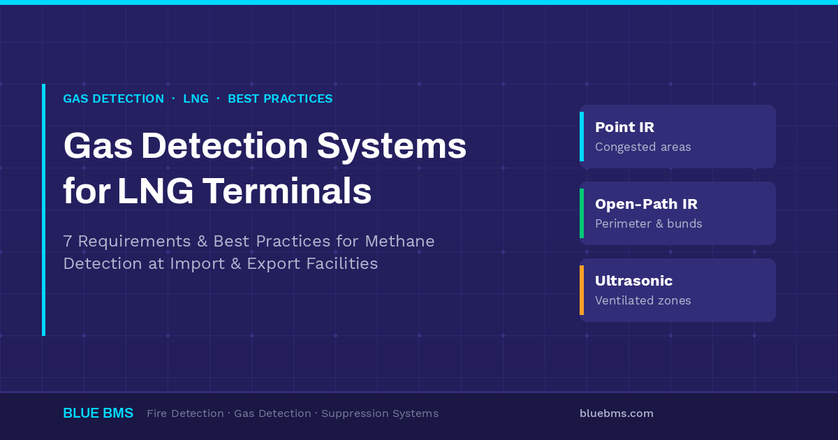
Gas detection systems for LNG terminals must detect methane releases fast enough to initiate shutdown before a flammable cloud reaches an ignition source. In practice, this means a layered architecture of point infrared, open-path infrared, and ultrasonic leak detectors, designed to NFPA 59A or EN 1473, verified by a coverage mapping study, and implemented as SIL 2 safety functions under IEC 61511.
This guide covers the 7 best practices for designing gas detection systems for LNG terminals, the applicable codes and standards, the detector technologies that work with cryogenic methane, and how to integrate detection into the terminal’s fire and gas (F&G) architecture.
Key Takeaways
- Infrared beats catalytic: IR point and open-path detection is the industry standard for gas detection systems for LNG terminals — fail-safe, poison-immune, and low-maintenance.
- Cold vapor behaves differently: LNG vapor is initially denser than air and hugs the ground before warming and rising — detector elevation strategy must reflect both phases.
- Ultrasonic fills the gaps: acoustic leak detection responds to high-pressure releases instantly, independent of wind direction — essential in open, ventilated areas.
- Mapping studies are now standard: performance-based 3D coverage verification has replaced rule-of-thumb detector spacing on modern LNG projects.
- SIL 2 across the loop: detection functions tied to ESD are safety instrumented functions under IEC 61511 and need certified hardware end-to-end.
Why Gas Detection Systems for LNG Terminals Face Unique Challenges
LNG is natural gas — predominantly methane — cooled to approximately -162 °C (-260 °F), which reduces its volume by a factor of roughly 600. When LNG leaks, three characteristics distinguish the hazard from typical hydrocarbon gas detection scenarios:
- Two-phase vapor behavior. Freshly vaporized LNG is colder and denser than air, so the vapor cloud initially spreads at grade level. As it absorbs heat, it becomes buoyant and rises. Detection layouts must cover both low-level pooling zones and elevated escape paths — a core design consideration for any gas detection system at an LNG terminal.
- Rapid vapor generation. One cubic meter of spilled LNG generates roughly 600 cubic meters of gas as it vaporizes, meaning even modest spills can produce large flammable clouds (methane LEL: approximately 5% by volume).
- Cryogenic secondary hazards. Cryogenic liquid contact embrittles carbon steel and injures personnel, so many terminals pair gas detection with low-temperature spill detection in impoundment basins and under transfer lines.
Add congested process areas (vaporizers, compressor bays), long jetty transfer lines, and large open storage areas, and no single detection technology can cover an LNG terminal alone. The result is the layered detection philosophy described below. For context on how the broader LNG and oil & gas market is driving investment in detection infrastructure, see our analysis of the European oil & gas market in 2026.

Codes and Standards Governing Gas Detection Systems for LNG Terminals
Gas detection requirements for gas detection systems for LNG terminals come from four regulatory layers. Most international projects must satisfy more than one simultaneously, and understanding the interplay is critical to avoiding specification conflicts during FEED:
| Standard / Code | Region / Scope | What It Governs for Gas Detection |
|---|---|---|
| NFPA 59A | North America, widely referenced globally | Requires flammable gas detection in enclosed buildings handling LNG or flammable refrigerants, at impoundment areas, and where leaks can credibly accumulate; ties detection to alarm and shutdown functions |
| EN 1473 | Europe (onshore LNG installations) | Risk-based approach requiring hazard assessment to determine detection coverage across storage, process, and transfer areas |
| IEC 61511 / IEC 61508 | International (functional safety) | SIL determination and verification for gas detection loops that initiate executive actions (typically SIL 2) |
| IEC 60079-29 series | International (detector performance) | Performance requirements, selection, installation, and maintenance of flammable gas detectors |
| ATEX / IECEx | EU / International (equipment certification) | Certification of detectors for installation in classified hazardous areas (Zone 1 / Zone 2) |
| ISO 28460 / SIGTTO guidance | Ship-shore interface | Detection and ESD linkage requirements at jetties and marine loading arms |
Best practice: treat NFPA 59A / EN 1473 as the minimum “where to detect” baseline, and use a facility-specific hazard analysis (HAZID/HAZOP plus dispersion modeling) to define the actual detection performance targets. Modern specifications for gas detection systems for LNG terminals are performance-based, not prescriptive — the code tells you what to protect, not how many detectors to install.
4 Detection Technologies Used in LNG Terminal Gas Detection Systems
Four technologies form the core of gas detection systems for LNG terminals. The table below summarizes where each fits in the layered architecture:
| Technology | How It Works | Best Applications at LNG Terminals | Limitations |
|---|---|---|---|
| Point infrared (IR) | Measures IR absorption of hydrocarbon gas at a fixed point | Congested process areas, vaporizer bays, pump shelters, HVAC intakes, analyzer shelters | Gas must reach the sensor; coverage is localized |
| Open-path infrared | IR beam between transmitter and receiver measures integrated gas concentration (LEL·m) along the path | Perimeter monitoring, tank bund boundaries, jetty approaches, fence-line detection between process and occupied areas | Beam blockage (fog, heavy rain, birds); alignment maintenance |
| Ultrasonic (acoustic) leak detection | Detects the ultrasound generated by pressurized gas escaping — no gas contact needed | Open, well-ventilated areas: compressor stations, metering skids, jetty transfer lines where wind disperses gas before it reaches IR detectors | Requires sufficient leak pressure (~2 bar+); detects leaks, not concentration |
| Low-temperature / cryogenic spill detection | Temperature elements or fiber-optic sensing detect cryogenic liquid contact | Impoundment basins, spill troughs, under loading arms and transfer line low points | Detects liquid spills only — complements, never replaces, gas detection |
Why infrared is the standard for LNG terminal gas detection systems
Catalytic bead sensors, still found in older facilities, have three failure modes that make them a poor fit for LNG service: they can be poisoned by silicones and sulfur compounds without indication, they fail to danger (a dead sensor reads zero gas), and they require oxygen to operate. Infrared detection fails safe by design — beam degradation triggers a fault, not a silent failure — and typically extends calibration intervals from months to a year or more, a significant OPEX reduction across the hundreds of detectors that gas detection systems for LNG terminals typically include. For more on how different detector technologies compare across applications, see the Blue BMS guide to fire & gas detection systems.
7 Best Practices for Gas Detection Systems at LNG Terminals
These best practices reflect the current engineering consensus for designing and implementing gas detection systems for LNG terminals on greenfield and brownfield projects:
1. Run a performance-based gas detection mapping study
Replace rule-of-thumb detector spacing with a 3D coverage mapping study that models credible leak scenarios against the proposed layout. Mapping verifies both geographic coverage (can a cloud of defined size pass undetected?) and scenario coverage (are the highest-risk leak sources monitored?). On modern LNG projects, owners and insurers increasingly require the mapping report as a FEED deliverable. Tools such as Kenexis Effigy and GexCon FLACS are widely used by specialist safety consultancies. For a deeper look at mapping methodology, the Kenexis gas mapping resource page provides a useful introduction.
2. Layer technologies instead of multiplying point detectors
A common design error is compensating for open-area coverage gaps by adding more point detectors. The better answer is layering: ultrasonic detectors for instant leak response in ventilated areas, open-path IR for perimeter and boundary monitoring, and point IR where gas can accumulate. Each layer catches what the others miss — this layered philosophy is the cornerstone of modern gas detection systems for LNG terminals.
3. Design detector elevations for cold, dense LNG vapor
Because fresh LNG vapor travels at grade before warming and rising, when specifying gas detection systems for LNG terminals, place low-level detection (typically 0.3–1 m above grade) around impoundments, transfer line low points, and bund walls — in addition to conventional elevations near potential leak sources. Open-path beams along bund tops are particularly effective at catching ground-hugging clouds leaving containment.
4. Use voted logic for executive actions
Single-detector trips cause spurious shutdowns; requiring confirmation from too many detectors delays response. Standard practice is 2ooN voting for executive actions (ESD, transfer shutdown, HVAC isolation) with single-detector low alarms for operator awareness. Typical setpoints: 20% LEL low alarm, 40–60% LEL high alarm for point detectors; 1 LEL·m low / 2–3 LEL·m high for open-path.
5. Treat ESD-initiating loops as SIL 2 safety functions
Gas detection functions that initiate shutdown are safety instrumented functions under IEC 61511. Specify SIL 2 certified detectors with published failure-rate data (FMEDA), route them through a certified logic solver, and document the verification calculation for the complete loop. Uncertified “SIL capable” claims without FMEDA data create schedule risk at the safety case review. This applies to all gas detection systems for LNG terminals where detection triggers executive action.
6. Protect the ship-shore interface with dedicated detection and ESD linkage
The jetty is the terminal’s highest-frequency transfer operation. Best practice combines ultrasonic detection along loading arms and manifolds, open-path coverage of the jetty approach, and integration with the linked ship-shore ESD system per ISO 28460 and SIGTTO guidance — so a confirmed release triggers coordinated shutdown on both sides of the interface.
7. Plan the maintenance philosophy at design stage
Detector accessibility, remote functional testing (e.g., magnetic test tools, automated open-path self-checks), and spares standardization determine lifetime cost more than purchase price. Standardizing transmitter platforms across the terminal reduces spares inventory and simplifies technician training — a strong argument for coordinating multi-vendor procurement of gas detection systems for LNG terminals through a single distribution partner.

Integrating Gas Detection Systems Into the LNG Terminal F&G Architecture
Gas detection systems for LNG terminals never operate in isolation. Detectors feed a fire and gas (F&G) system — either a dedicated F&G logic solver or the plant safety PLC — which executes the cause-and-effect matrix: alarms, HVAC isolation, ignition source removal, ESD initiation, and deluge or dry chemical release where flame detection confirms fire. A typical architecture combines:
- An addressable fire detection backbone such as Autronica AutroSafe 4 (SIL 2 certified at system level) covering buildings, substations, control rooms, and technical spaces;
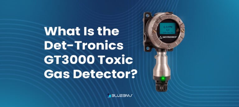
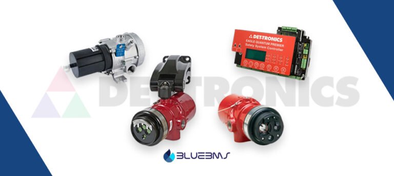
- Hardwired 4–20 mA/HART gas detectors from leading manufacturers — Honeywell, MSA, Dräger, Det-Tronics, or Teledyne — integrated into the F&G logic solver for executive actions;
- IR3/multispectrum flame detectors covering open process areas per the fire hazard mapping study;
- Modbus/OPC links exposing detector health and analog values to the DCS, historian, and maintenance systems (CMMS) for condition-based monitoring.
For a broader look at how detection, suppression, and shutdown work together on industrial facilities, see our guide to integrated fire, gas, and suppression systems. And for guidance on selecting the right detector vendors for EPC projects, read our comparison of fire and gas detection vendors.
Choosing Gas Detection Equipment for LNG Terminal Projects
When specifying gas detection systems for LNG terminals, EPC contractors and owner engineers typically evaluate vendors on six criteria: certification coverage (ATEX, IECEx, FM, marine class), SIL 2 capability with published FMEDA data, integration with the plant’s safety PLC or logic solver, technology fit for the specific hazards present, documentation quality for FEED and detail engineering, and regional support during commissioning.
Most LNG projects combine 2–4 brands under one integrated architecture. Working with a specialized multi-brand distributor simplifies procurement, ensures compatibility across manufacturers, and consolidates logistics and documentation into a single point of accountability.
Specifying Gas Detection Systems for LNG Terminals?
Blue BMS is a global distributor of gas detection, flame detection, fire detection, and fire suppression systems for LNG, oil & gas, and industrial EPC projects. From FEED-stage specification support to consolidated multi-vendor procurement and delivery across Europe, North Africa, the Gulf, and the Americas — we help EPC contractors and terminal operators source complete F&G scopes through one partner.
Frequently Asked Questions About Gas Detection Systems for LNG Terminals
What gas detection systems are required for LNG terminals?
Gas detection systems for LNG terminals must provide flammable gas (methane) detection in enclosed buildings handling LNG, at impoundment areas, transfer points, and anywhere leaks can credibly accumulate — typically implemented as a layered combination of point IR, open-path IR, and ultrasonic detectors. NFPA 59A and EN 1473 define where detection is required; IEC 61511 defines the safety integrity requirements for the detection loops.
Why are catalytic bead detectors not recommended for LNG terminals?
Catalytic sensors can be poisoned without warning, fail to danger (a dead sensor reads zero), and need oxygen to function. Infrared detection is immune to poisoning, fails safe by design, operates in oxygen-depleted atmospheres, and needs far less calibration — which is why IR is the default methane detection technology at modern LNG facilities.
What alarm setpoints are typical for LNG terminal gas detection systems?
Common practice is 20% LEL low alarm and 40–60% LEL high alarm for point detectors, and 1 LEL·m low / 2–3 LEL·m high for open-path detectors. High alarms initiate executive actions through voted logic — typically 2ooN — to balance fast response against spurious shutdown risk. Final setpoints are always confirmed by the project’s safety requirement specification (SRS).
What is a gas detection mapping study?
A mapping study uses 3D modeling of the facility to verify that the proposed gas detector layout detects credible leak scenarios, accounting for equipment congestion, ventilation, and cold-vapor dispersion behavior. It has become standard practice on LNG projects and is increasingly requested by owners and insurers as evidence of performance-based coverage.
Do LNG terminals need SIL-rated gas detection systems?
Yes — gas detection functions that initiate emergency shutdown are safety instrumented functions under IEC 61511 and typically require SIL 2 capability across the complete loop: certified detector, certified logic solver, and final element, supported by documented failure-rate (FMEDA) data for SIL verification calculations.
Published by the Blue BMS Engineering Team — specialists in fire detection, gas detection, and suppression systems for LNG, oil & gas, and industrial projects worldwide.
Last updated: July 2026 · Reviewed against current editions of NFPA 59A, EN 1473, IEC 61511, and IEC 60079-29.