Definitive Guide to Decoding the Fire Alarm System Wiring Diagram
For the modern systems integrator or electrical installer, a fire alarm system wiring diagram is more than just a schematic—it is a life-safety contract. Unlike data cabling or standard electrical distribution, fire alarm wiring is governed by a rigid set of codes designed to ensure that when a crisis occurs, the system survives long enough to save lives.
Whether you are retrofitting a conventional panel in a small retail space or designing a complex addressable network for a high-rise, understanding the nuances of circuit classes, supervision, and NEC compliance is non-negotiable. This guide dives deep into the technical architecture of fire alarm systems, offering practical tips to keep your installations code-compliant and false-alarm-free.
The Governing Law: NEC Article 760
Before interpreting any wiring diagram, you must understand the rules of the road. In the United States, National Electrical Code (NEC) Article 760 is the bible for fire alarm installations. It specifically covers the installation of wiring and equipment, distinguishing between two critical power categories:
- NPLFA (Non-Power-Limited Fire Alarm) Circuits: These can operate up to 600V and are essentially handled like standard electrical branch circuits. They require heavier gauge wire and stricter conduit rules.
- PLFA (Power-Limited Fire Alarm) Circuits: This is what most integrators work with today. These circuits operate at lower voltages (typically 24VDC) with power limited by a listed source (like the Fire Alarm Control Panel). Because the power is limited, the risk of shock and fire is reduced, allowing for more flexible wiring methods.
Pro Tip for Installers: Never mix PLFA and NPLFA conductors in the same raceway or enclosure unless they are separated by a barrier. This is a common inspection failure point.
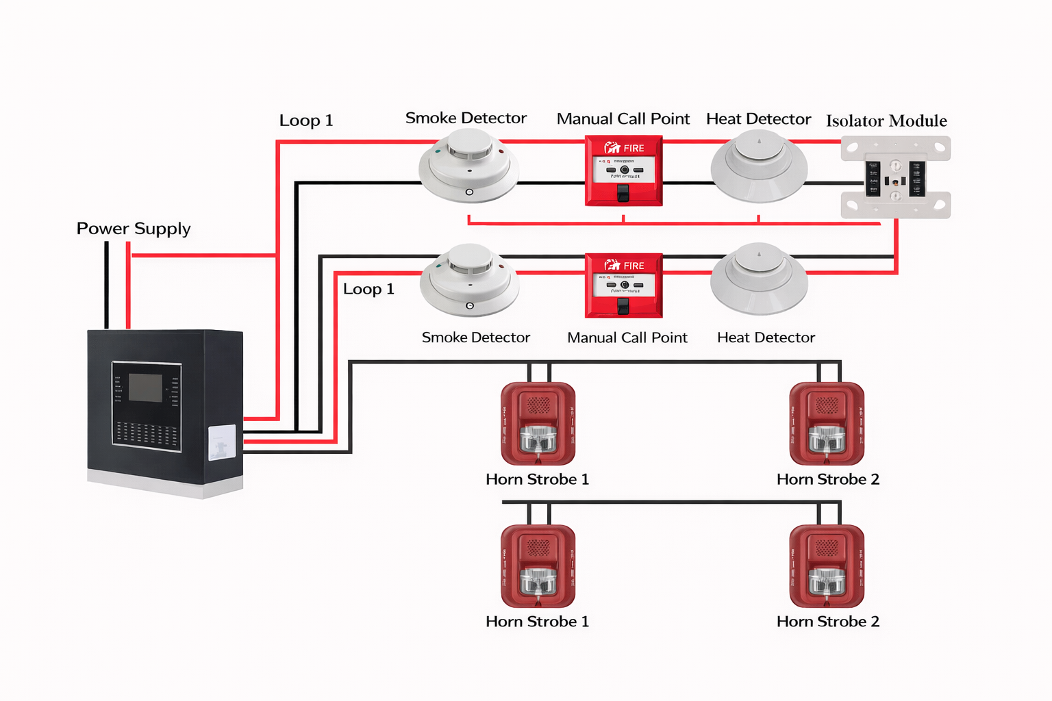
Understanding the Big Three Circuits in a Fire Alarm System Wiring Diagram
When you look at a fire alarm control panel wiring diagram, you are generally looking at three distinct types of signal paths. Understanding the difference is vital for troubleshooting.
1. IDC (Initiating Device Circuit)
Used primarily in conventional systems, the IDC connects input devices like smoke detectors, heat detectors, and manual pull stations.
- How it works: The devices are wired in parallel. The panel monitors the circuit by passing a small current through an End-of-Line Resistor (EOLR) at the very end of the wire run.
- The Logic: If a detector activates, it shorts the circuit, increasing current flow (Alarm). If the wire breaks, the current stops (Trouble).
2. NAC (Notification Appliance Circuit)
This is the output side. It powers horns, strobes, and speakers.
- The “Polarity Reversal” Trick: In standby mode, the panel sends a reverse polarity voltage through the circuit to check the EOLR for continuity. When an alarm occurs, the panel reverses the polarity, allowing the diodes in the horns/strobes to conduct power and activate the devices.
- Synchronization: Modern diagrams often require a sync module (or built-in sync protocol) to ensure strobes flash in unison, preventing photosensitive epilepsy issues.
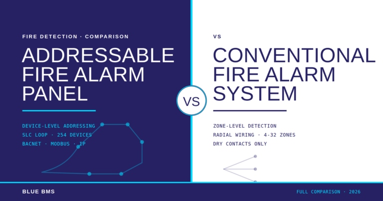
3. SLC (Signaling Line Circuit)
The heartbeat of modern addressable systems. The SLC carries data and power to intelligent detectors and modules.
- The Advantage: Unlike the IDC, the SLC allows the panel to identify exactly which device is in alarm. It also supports “T-Tapping” (branching) in Class B configurations, which can significantly reduce cabling labor.
Class A vs. Class B: The Architecture of Redundancy
The most significant decision in designing a wiring diagram is the choice of Class (formerly known as Styles). This dictates how the system behaves when a wire is cut.
Class B (The Radial Stub)
In a Class B diagram, the wire leaves the panel, hits every device, and terminates at the last device with a resistor (conventional) or simply stops (addressable).
- The Risk: If the wire breaks in the middle, every device past the break is lost. The panel will report a “Trouble,” but that zone is effectively dead until fixed.
- Best Use: Smaller facilities where the budget is tight and the distance to the end of the line is short.
Class A (The Redundant Loop)
Class A wiring leaves the panel, connects to all devices, and then returns to the panel on a separate set of terminals.
- The Benefit: If the wire breaks, the panel detects the open circuit but immediately feeds the loop from both ends. No devices are lost.
- Installation Requirement: To be truly redundant, the outgoing and return paths require physical separation (often 1 to 4 feet depending on local codes) to ensure a single event (like a forklift hitting a conduit) doesn’t cut both legs.
Class X (The “Short” Proof Loop)
Formerly Style 7, Class X is a Class A loop equipped with isolator modules. If a short circuit occurs (e.g., wires touching), the isolators disconnect only the affected segment, keeping the rest of the loop operational. This is often mandatory in high-rise and mission-critical environments.
Essential Wiring Rules for the Field
Even the best diagram fails if the physical installation is poor. Here are three rules every installer must memorize:
1. The “Do Not Loop” Rule
When connecting a device, never wrap a continuous wire around the terminal screw. You must cut the wire and terminate both ends into the terminal (or use the separate in/out terminals).
- Why? If the wire is continuous and the device falls off the ceiling, the circuit remains closed, and the panel never knows a device is missing. By cutting the wire, a loose device breaks the circuit, triggering a “Trouble” signal that alerts the facility manager.
2. Location of the EOLR
In Class B conventional systems, the End-of-Line Resistor must be at the actual end of the line, effectively acting as the last device.
- Common Mistake: Placing the resistor inside the control panel. This “tricks” the panel into seeing a complete circuit even if the field wiring is completely severed.
3. Monitoring Auxiliary Power
When using 4-wire smoke detectors (which require a separate power pair), you must supervise the power wires. If the power supply dies, the detector stops working, but the panel won’t know because the alarm contact loop is still intact.
- The Solution: Use an End-of-Line Relay (like the EOLR-1). The relay coil is energized by the 12/24V power. Its contacts are wired in series with the zone’s EOL resistor. If power drops, the relay opens, breaking the zone loop and sending a trouble signal to the panel.
Advanced Logic: Elevator Recall and Shunt Trip
Integrating fire alarms with elevators is one of the most complex aspects of a wiring diagram. It generally requires three specific signals sent from the fire panel to the elevator controller:
- Primary Recall: Activated by smoke detectors in the elevator lobby on any floor except the designated egress floor. This sends the cars to the main floor.
- Alternate Recall: Activated by the smoke detector on the main lobby floor. This sends the cars to a secondary floor (so occupants don’t exit into a fire).
- Fire Hat (Flash): Activated by a detector in the hoistway or machine room. This flashes the hat icon in the cab, warning firefighters that the shaft itself is unsafe.
The Shunt Trip Danger: If the elevator shaft or machine room has fire sprinklers, the elevator power must be cut before the water turns on to prevent erratic brake behavior. This is done via a Shunt Trip breaker triggered by a heat detector located near the sprinkler head. The heat detector must have a lower temperature rating and higher sensitivity (RTI) than the sprinkler head to ensure it trips first.
Conclusion: Documentation is Key
A fire alarm system is a living entity. Over time, devices are added, and layouts change. NFPA 72 requires that “As-Built” drawings (record drawings) be maintained on-site. These diagrams should clearly identify the location of every EOLR, the address of every SLC device, and the logic of every relay.
For the professional integrator, mastering the wiring diagram is about ensuring that when the system is tested—or worse, when it is truly needed—the path from detection to notification is unbroken, compliant, and reliable.